A custom display base starts with the model and its intended pose. The shape of the plinth comes later. Before choosing a color or adding a nameplate, decide what the base must support, where it will sit, and which surfaces will remain visible.
Separate decoration from support. A decorative plinth beneath an existing stand is a different project from a structure intended to hold a model above the shelf. Artrovo Gundam needs that distinction in the brief to assess an original FDM printing request.
Define the display job
Choose one primary purpose: elevate a standing model, organize several compatible commercial stands, create a themed scenic platform, or support an original custom arrangement. Explain whether the model will be stationary or moved frequently.
Then describe the failure you need to avoid. A base that slides on a smooth shelf presents a different problem from one that tips under an extended accessory. Simply asking for a “strong stand” leaves those design requirements hidden.
If an existing manufacturer stand already supports the model correctly, retaining it and designing an original platform around its footprint may be a useful direction. Any mounting or retention arrangement still needs review; a recess shaped like a stand is not automatically a secure attachment.
Measure the display envelope
Measure in the pose you intend to use. Include the ends of weapons, wings, effects, and accessories rather than measuring only the torso. Record the maximum width, depth, and height, plus the available shelf space and clearance above it.
Use consistent units and label them. A photograph beside a ruler can provide context, but a written dimension is much easier to interpret. Mark which measurements are firm limits and which are approximate preferences.
Maximum available shelf width and depth.
Model and accessory footprint in the intended pose.
Desired base height and overhead clearance.
Dimensions of any existing stand that must sit on the platform.
Approximate total supported mass, with a note if it has not been measured.
A drawing does not need to look polished. A clear top view and side view with dimensions are more useful than an attractive perspective image with no scale.
Describe the load and attachment
Show where the model or stand will contact the base. Identify whether it will simply rest there, fit into a pocket, or use a separately reviewed attachment. Include any existing hardware and the measurements needed to understand it.
Tell us if the pose places weight away from the center. Long accessories and elevated poses change the problem even when the model’s total mass is modest. A wide decorative outline alone does not establish stability or a safe load rating.
Do not order an unreviewed printed connector on the assumption that a familiar-looking hole will fit. Clearances, material, orientation, and the actual contact geometry need to be considered together. Fit tests or a prototype may be appropriate before a final display component.
Choose the visible surfaces
FDM prints are built in layers. State which faces will be seen from the normal viewing direction and whether you plan to sand, paint, or otherwise finish the print. This helps frame the discussion about orientation, supports, and surface expectations.
For a base viewed mainly from above, the top and front may matter most. For a freestanding display, the sides and back may be equally visible. Raised lettering, shallow recesses, and sharp decorative features should be checked against the printing and finishing plan.
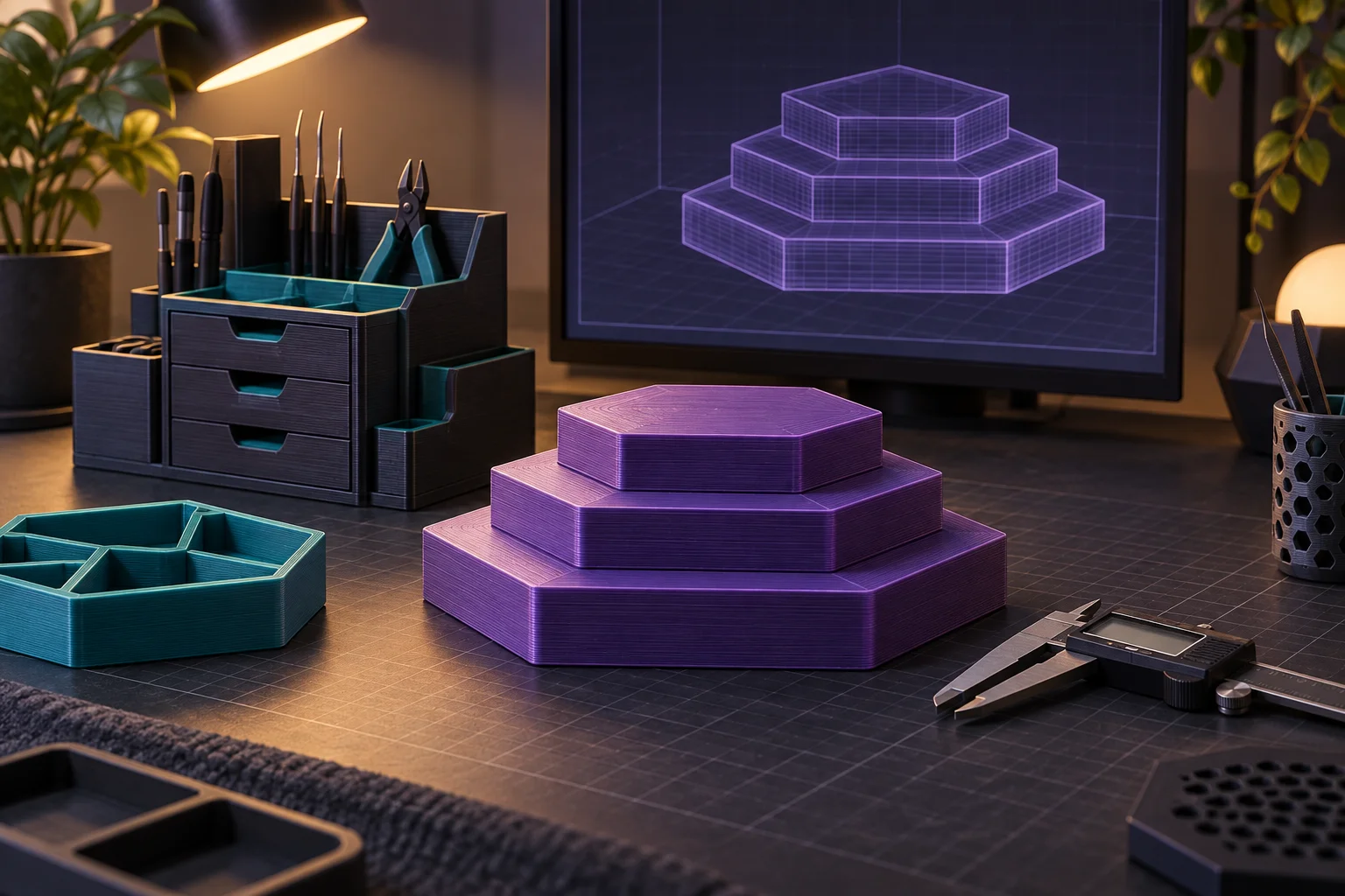
The diagrams in this guide are planning illustrations, not photographs of delivered prints or evidence of a tested load capacity. Your final geometry and print settings require their own review.
Build an original design brief
Artrovo Gundam offers FDM printing for original or authorized work. Bring your own design or a file whose license permits the intended printing arrangement. Keep the source and license information with the request.
A general industrial platform, geometric plinth, or original nameplate can communicate a theme without copying a manufacturer’s part. The service is not for reproducing official kit components. Genuine replacement parts belong in the support and Bounty Board routes.
A brief you can copy and complete
Purpose: [decorative platform / reviewed support project]. Model and pose: [description]. Available space: [width × depth × height, units]. Contact points: [description and dimensions]. Supported mass: [measured value or unknown]. Visible faces: [top/front/sides]. Environment: [indoor location, possible heat or sunlight]. Finish: [raw printed color or planned finishing]. File and rights: [source and permission]. Quantity: [number].
Add a simple sketch and any relevant photographs of your own setup. List unresolved questions explicitly. “Attachment method undecided” is more helpful than an unlabeled hole in a file that appears final.
Send the project for review
Review Artrovo Gundam’s design guidance and current materials, then use the quote workflow. For file preparation, see how to prepare a clear FDM print request.
State a desired deadline as a request, not an assumption. Review time, geometry, material availability, printing, and any testing affect feasibility. A clear brief lets the conversation focus on making the display work in its actual setting.